We cant have functional failure in our design. End cap Cells.

End Cap Or Boundary Cell Use Of Endcap Cells Placement Of Endcap Cell Layout Of Endcap Cell Youtube
There are various reasons for the instant large current requirement in the circuit and if there are no adequate measures have taken to handle this requirement power.
. Well-Tap Cells and End-Cap Cells. Before starting the actual placement of the standard cells present in the synthesized netlist we need to place various physical only cells like end-cap cells well-tap cells IO buffers antenna diodes and spare cells. EndCap Cells These cells are inserted to take care of boundary DRC of Wells Other layers.
END CAP CELLS End cap cells are pre placed physical only cells it has only physical connectivity End cap cells are placed at the end. This is a physical-only cell. Decap Cells Decoupling capacitors are another type of physical only cells used in PD flow.
-Insert to meet certain design rules -Insert at the end of the site row top and bottom side of the block boundary and every macro boundary. What are the challenges you faced in your design. Their layout is different from that of a filler or Dcap 2.
What are the OCV AOCV. Tie Cell insertion 10. To report the number of inputs dbGet topnumInputs 2To report the number of instances dbGet topnumInsts 3.
These are used to address boundary N-Well issues for DRC cleanup. They connect only to the power and ground rails once power rails are created in the design. If you say congestion timing latency then they will ask more question on these challenges.
END cap cells are used for N WELL continuity and also main reason is characterization team will create a library for a cell is adjoin with other cells. To avoid drain and source short. Tap-gate spacing has to be met while adding well-tap array.
The library cells do not have cell connectivity as they are only connected to power and ground rails thus to ensure that gaps do not occur between well and implant layer and to prevent the DRC violations by satisfying well tie-off requirements for core rows we use end-cap cells. To avoid the base layer DRC Nwell and Implant layer at the boundary. So to avoid any kind of functional failure due to Dynamic IR we use Decap cells in our design.
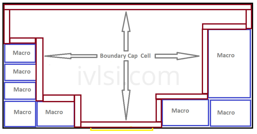
End cap cells are also known as boundary cells. This prevents DRC violations by satisfying well tie-off requirements for the core rows. A typical view after preplacement has shown in figure-1.
The end cap cells are placed in the design because of the following reasons. A filler or Dcap cells actually helps in continuity of n-well. So thats the reason we are giving END cap cells at the.
Boundary cap cells are placed just after macro placement in the floorplan flow. What is end cap cell or Boundary cell What is the use of end cap cells in ASIC Design. What are the inputs of Physical design.
Boundary cells consist of end-cap cells which are added to the ends of the cell rows and around the boundaries of objects such as the core area hard macros blockages and voltage areas and corner cells which fill the empty space between horizontal and vertical end-cap cells. Posted on June 17 2015 by vijayec488. End Cap Cells and how to place end cap cells in the design.
These do not have any logical functionality. What is Boundary Cap End Cap. These cells prevent the cell damage during fabrication.
To protect the gate of a standard cell placed near the boundary from damage during manufacturing. JTAG and Other Cells Close to the IOs. Libraries In Physical Design.
These library cells do not have signal connectivity. Decap cells are basically a charge storing device made of the capacitors and used to support the instant current requirement in the power delivery network. Used for row connectivity and specifying row ending.
It breaks the n-well in a way avoiding any DRCs. End cap Cells. END CAP CELLS End cap cells are pre placed physical only cells it has only physical connectivity End cap cells are placed at the end.
End Cap Cells ensure proper terminations of rows so that no DRC are created. End cap cells in Physical design - Free download as PDF File pdf Text File txt or read online for free. Boundary cap cells are placed to have N-Well tie-off.
Current I Increases near inductor so L d Id t increases due to which Voltage. It is used to isolate several designs and IPs in a SOC. Let us continue with the physical only cells present in the standard cell libraries that ease the digital PD flow.
We have explained all about end cap cells in this session with the he. End-cap cells are preplaced physical-only cells required to meet certaindesign rules and placed at the ends of the site rows by satisfying well tie-off requirements for the core rows These library cells do not have any signal connectivity They connect only to the power and ground rails once power rails are created in the design. Boundary cells does exact opposite of it.
What are the content in the lib lef tlef files. Boundary cap cells are physical only cells. So Well-taps cells are added in partitionchip level to tie the wells to VDDVSS.
Filler Cells Once you have completed placement and routing there are usually gaps left in the layout where you do not have any standard cells present. These cells are placed at the periphery of the core and power domain. Fig1 End-cap cells are typically nonlogic cells such as a decoupling capacitor for the power rail.
What is value of Tran cap latency and skew in your design. Decap cell is basically a capacitor cell which is used temporarily in the design between power and ground rails to counter the functional failure. Filler Cells Well Tap Cells Decap Cells.
-This are the preplaced physical only cells. - This will also helps to reduce the drcs nearer to macros as the standard cells do not placed near to the macros. It is not possible to abut every cell available as that would cause.
Optimizing and Reordering Scan Chains. These cells are placed in an array one after another. IO cell pad cell Libraries.
They also ensure that gaps do not occur between the well and implant layers. End Cap Cells. DeCap Cells in Physical Design Use of Decap Cells in PD.
These cells essentially act as a capacitance between power and ground rails and hence as a charge reservoir that can be counted upon while there is a high demand for current from the power lines. Placements checks Congestion If the congestion is there in your design first check in which region you got the congestion hotspot If it is with cell density u.

Welcome To The World Of Physical Design Different Types Of Physical Cells

Team Vlsi End Cap Cells In Vlsi Boundary Cells In Vlsi

Physical Only Cells Vlsi Physical Design For Freshers

Team Vlsi End Cap Cells In Vlsi Boundary Cells In Vlsi

Physical Only Cells Vlsi Physical Design For Freshers

Vlsi Design End Cap Cells

Physical Only Cells Vlsi Physical Design For Freshers
Boundary Cap Cells End Cap Placement Ivlsi
0 comments
Post a Comment